What is a VFD? - Variable Frequency Drive
- Jonathan Gee
- Apr 22, 2021
- 5 min read
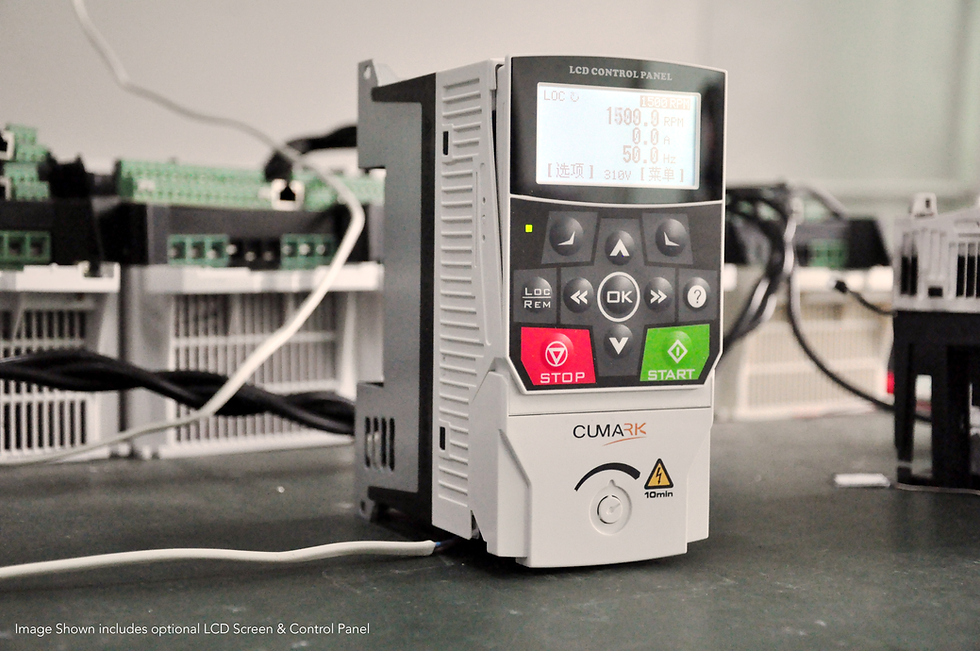
STATE-OF-THE-ART VARIABLE FREQUENCY DRIVES FROM EMG PRECISION
Depending on the application, the term "VFD" can refer to two different types of equipment. A VFD is technically made up of a Variable Frequency Controller and an Operator Interface. It has standard input power (60 or 50 Hz Sine Wave), variable frequency output power (square wave), and external control connections (sensors, building automation controls, building management systems).
For the purposes of this post, we'll refer to this as a "Stand Alone VFD." A “Stand Alone VFD” coupled with an overcurrent protective device (OCPD), such as a circuit breaker or fuses, is another common configuration. This will be referred to as a "Combination VFD." Despite the fact that the industry uses the same name for both configurations, the two systems are slightly different. Similarly, we use the term "Motor Starter" to refer to the contactors and coils that connect the motor to the power sources, and "Combination Motor Starter" to refer to a "Motor Starter" that is coupled with a fused disconnect.
Protection Against Overcurrent
Overcurrent protection for a VFD can be provided by either circuit breakers or fuses. Fuses are less likely to cause nuisance outages than circuit breakers and are a better choice for high-fault current circuits. However, if not properly equipped with phase-loss detection, fuses can drop out one leg of a three-phase circuit and cause damage to a motor. Circuit breakers can be easily reset if tripped and do not necessitate the storage of spares, which can be costly.


Method of Control
Variable frequency drives (VFDs) are frequently used to control variable motorised operations as part of building mechanical processes or HVAC systems. Start/stop, change speed, constant speed, limits, ramping, forward/reverse, and energy conservation are examples of these operations. The commands for these operations are communicated to the VFD via some type of operator interface, the most basic of which is local manual control via an external switch, push button, or keypad. Other more sophisticated methods, such as automatic control from an external process control signal, are available. Remote control signals generated as digital or analogue inputs, digital/relay or analogue outputs from some control device associated with the equipment tasked with providing variable control to the motor are examples of these methods. A voltage range (0 – 10 Vdc), current range (0 – 20 mA) from a temperature sensor or pressure transducer, or a set of dry contacts on a control relay are examples of these signals. Multiple motors on a single drive, lead/follow, closed loop/PID, and cascade control cards are examples of other control methods (fixed and variable stages). A building automation system (BAS) can be used to enable or disable VFD control of a motorised process by utilising a variety of data such as schedules, energy optimization, and electrical demand limiting. The DDC may also send a reference signal command corresponding to the motor speed required to maintain a control set point. A serial communications protocol can be used to allow a DDC controller to communicate directly with a VFD over a LAN or Bus (RS-485 connection). Ethernet protocols such as BACNet and LonWorks, for example, form more of a Global Network of multiple control systems hosted by a PC-based graphic user interface (GUI).
Enclosures
It is critical to provide the proper enclosure for the surrounding environment. There are standard NEMA (National Electrical Manufacturers Association) configurations that dictate what environment an enclosure should be rated for. NEMA 1 is intended for use in standard locations. The majority of indoor applications will be housed in a NEMA 1 enclosure. NEMA 3R is designed for use in wet environments. VFDs installed outside or in wet locations inside will be protected by a NEMA 3R enclosure.

Do I need a line reactor?
Line Reactors are used to protect the VFD from harmful distribution system disturbances (surges, spikes, transients, etc.) and to prevent harmonics produced by the VFD from bouncing back onto the distribution system. They are connected in series with the VFD on the VFD's line side. Load Reactors are used on the VFD's load side to protect the motor and wiring when the distance between the VFD and the motor is very long. Noise spikes and high frequency waves generate high voltage. The cable insulation is not rated for high voltage spikes and will deteriorate over time. A Load Reactor should be installed for distances greater than 100 feet, as a general rule.
How should I connect a VFD?
The load-side cables are subjected to high voltage, intense heat from corona discharge, and electromagnetic interference when used with VFDs. Standard PVC-insulated single wire conductors are not designed to withstand these effects and may even cause additional issues. The VFD cables' cross-linked polyethylene insulation can withstand the intense heat produced by the corona discharge. Shielding within the cable prevents EMI from escaping and being picked up by other nearby equipment. The variable frequency drive's high voltage wave effect is reduced by cable geometry and grounding. VFD cables should be used on the load-side of the VFD, from the VFD all the way to the motor.
Finally, mechanical systems cannot function without control and power. VFDs are a great way to fine-tune the operation of your mechanical system, but they are more of a boat anchor if they do not function properly with the control and power requirements. These electrical considerations will enable a VFD to make your system work as intended by the mechanical engineer.
Why should I use a VFD?
1 - Lower Energy Consumption and Costs
If you have an application that does not require full speed, you can save energy by controlling the motor with a variable frequency drive, which is one of the benefits of Variable Frequency Drives. VFDs enable you to match the speed of motor-driven equipment to the load. There is no other means of controlling an AC electric motor that allows you to do this. Electric motor systems account for more than 65 percent of industrial power consumption today. Motor control system optimization, such as installing and upgrading to VFDs, can reduce energy consumption in your facility by up to 70%. Moreover, the use of VFDs improves product quality whilst also reducing production costs.
2 - Increase Production with Tighter Process Controls
By running your motors at the most efficient speed for your application, you will make fewer mistakes and thus increase production levels, which will earn your company more money. You eliminate jerks on conveyors and belts, allowing for higher throughput.
3 - Extend the Life of Equipment and Reduce Maintenance
When your equipment is controlled by VFDs, which ensure optimal motor application speed, it will last longer and have less downtime due to maintenance. Because of the VFD's optimal control of the motor's frequency and voltage, it will protect your motor from issues such as electro thermal overloads, phase protection, undervoltage, overvoltage, and so on. When you start a load with a VFD, the motor or driven load is not subjected to the "instant shock" of across-the-line starting, but can start smoothly, reducing belt, gear, and bearing wear. Because we can have smooth acceleration and deceleration cycles, it is also an excellent way to reduce and/or eliminate water hammer.
Well if you're reading this, then kudos to you for getting this far. We hope you enjoyed this article. You should not use this article as a basis for connecting a VFD. You should always rely on professional, qualified and competent persons to install your electrical equipment. This is purely an introductory guide to VFD's and maybe subject to errors and/or omissions.
Jonathan Gee
EMG Precision

Comments